Multiple materials and complex geometriesSPECIAL JOINT / METAL AM
φ140×190mmExample metal AM build size
Depends on equipment and geometry
LPBFLaser powder bed fusion
For complex internal flow paths
IntegrationFewer joints
Feasibility reviewed in advance
METAL ADDITIVEMetal additive manufacturing
Design the flow path,not an assembly.
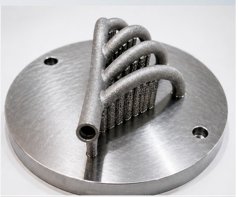
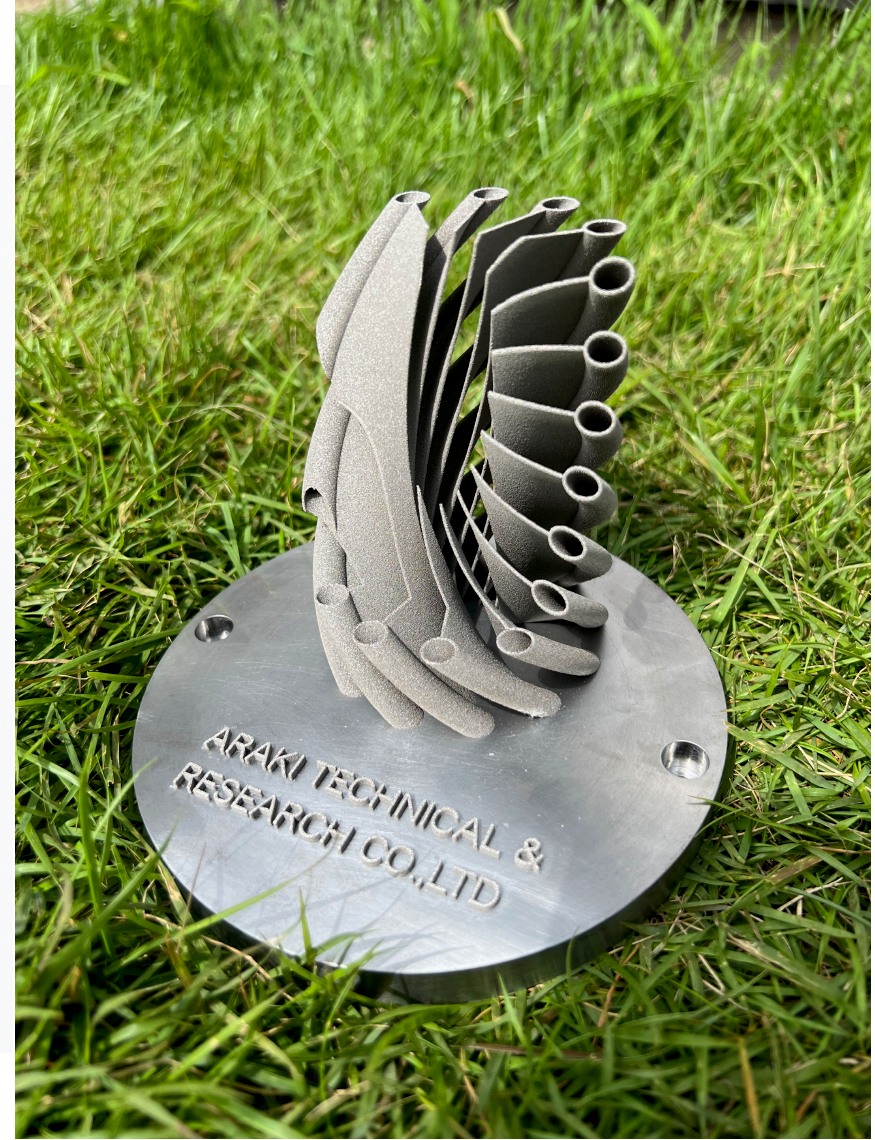
Where conventional construction assembles a complex branch from separate parts, metal additive manufacturing designs it as one piece, internal flow path included. Joints disappear and the flow stays smooth and continuous.
CONVENTIONAL
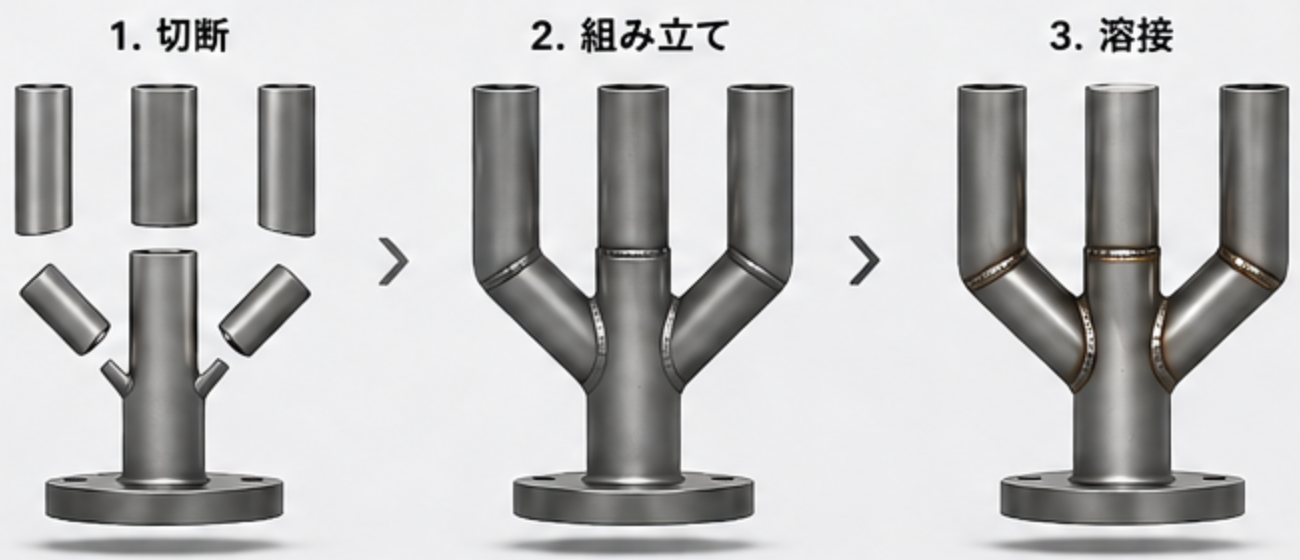
Conventional fabrication | Welded assembly
01CuttingEach branch pipe machined separately
02AssemblyAlign position and angle
03WeldingJoin at multiple points
Multi-point welding makes it difficult to build
Flow is easily disturbed at the joints
Quality depends on operator skill
More points to manage for contamination and leaks
ENGINEERED FLOW
Metal additive manufacturing | Integrated flow path
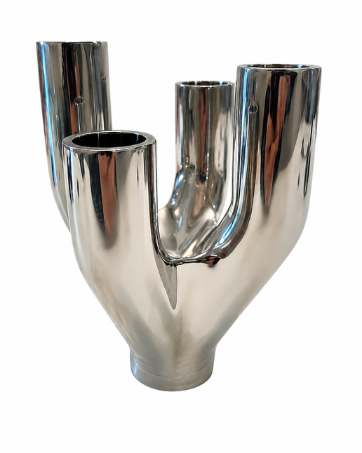
Seamless integrated structure
A continuous internal flow path reduces turbulence, stagnation, and pressure loss.
A one-piece structure with no welds
A smooth, continuous internal flow path
Complex geometry reproduced as designed
Quality control points consolidated
Weld pointsMany→None
Internal flow pathDiscontinuous→Smooth
Contamination riskHigh→Reduced
Design freedomConstrained→High
Pressure loss can be reduced by up to 50%※* Simplified flow-analysis figures under our assumed conditions. Results vary with operating conditions and geometry.
ENGINEERED FLOW / 40A–32A
Move from welded assembly to an integrated flow-path design.
A complex branch that would otherwise be cut, aligned and welded at many points is designed as a single form with a continuous internal flow path. Fewer joints means flow, cleanliness and repeatability can be addressed together. Surface finishing after building is available up to #400 polish.
INLET
40A
OUTLET
32A × 4
MATERIAL
SUS316L
STRUCTURE
Seamless one-piece structure
SANITARY MANIFOLD / 2S
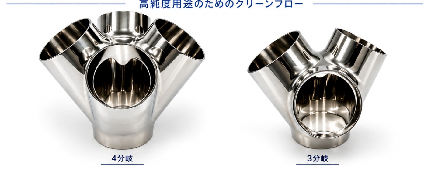
Clean flow for high-purity applications.
Three- and four-outlet sanitary manifolds can also be designed as smooth flow paths with few joints.
01
Smooth flow path
Internal geometry designed for continuous flow.
02
Low contamination
A design that reduces seams and dead zones.
03
High reliability
A one-piece structure with minimal welding.
04
Design freedom
Flow paths optimised for the application.
LPBF / ADDITIVE MANUFACTURING
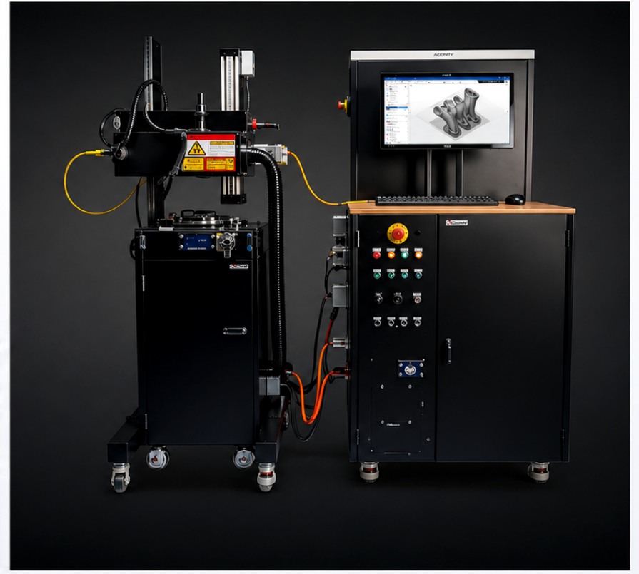
A metal powder additive manufacturing system for precise builds.
Laser powder bed fusion (L-PBF) builds internal flow paths, thin-walled structures and complex geometries that are difficult to cut or weld. Build preheat reaches up to 800°C. The system is also used for metal powder development, where we have a track record. We design the whole route — building, machining, polishing and inspection — so the result stands up as a product.
BUILD SIZEφ140 × 190 mm
SYSTEMACONITY MINI
PREHEATUp to 800°C
MATERIAL / SAMPLE
Select materials and processes for the application.
Material is selected from your requirements for corrosion resistance, strength, heat resistance or weight. Rather than replacing everything with 3D printing, we also propose combinations with pipe forming, machining, polishing and welding.
SUS316L
M300F
Inconel 718
AZX912
* Feasibility is assessed individually against geometry, dimensions, quality requirements and post-processing conditions.
WORKFLOW
From concept to product
01Flow-path and specification review
023D design and build review
03Printing, post-processing, and inspection
CONTACTConsult us about Metal AM & Special Fittings
Consult our engineers before your requirements are finalized.
Send whatever you have — drawings, notes, images or site photographs. From the application, material, size, quantity and your current problem, we work out the manufacturing method together.